C2 PROJECT
C2 Project News
March 2026
Frustrations and successes
After many weeks of work Andrew has completed milling the crosshead slippers, and so, understandably, decided he'd seen enough of the crossheads for a while. It was therefore time to return to work on the expansion links.
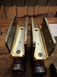
The expansion links each have four holes to take the fitted bolts which hold the cover plates on. The precise location of the cover plates is important because the trunnions about which the expansion links oscillate are located on them.
On the day before the working party, Marek had kindly helped Andrew devise a clamping method to hold the expansion link assemblies onto the bed of the Chinese CNC milling machine. This was to later prove very useful when machining the holes. Andrew also welded the plugs into the bosses on the expansion link covers, so that they were ready for re-drilling.
Last month Chris devised a method for locating the die block in the "middle" of the expansion link, which made it possible to line up the trunnions on the cover plates with it. Andrew was convinced that he could position the die block within about 0.5mm of its nominal "middle" position; not easy when there is no hard datum to work to. He found that it was very difficult to tighten the engineer's clamps firmly enough to prevent them dropping out as soon as the assembly was moved. This caused a lot of frustration, and it took several hours to work out the optimum arrangement.
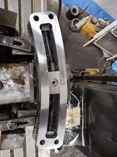
Die block clamped in the nominal mid gear position to allow the cover plates to be lined up correctly. - March 2026
We now wanted to align both cover plates on each expansion link so that they could all be reamed together. The existing dowel wasn't long enough, so Dave offered to cut a longer one. It was a simple case of parting off a section of bar already of the correct diameter, but as the cut was made, crack! The parting tool tip broke. Very annoying! Fortunately parting tool tips are replaceable, and the cut/chewed end of the dowel could be faced off to make it usable.
Andrew then found that the dowel fitted into three of the four holes in the rear of the cover plate trunnions, but was too big to fit in the fourth hole. This was odd, given that all four holes had been drilled using the same drill bit. Perhaps the drill wandered less when forming the last hole. It took Andrew some time with emery paper to enlarge the offending hole just enough for the dowel to slide in. Again, very frustrating!
Having got everything lined up, we now found that the holes for the pins which link the return rods to the expansion links weren't quite aligned. So everything had to come apart such that Andrew could run a reamer through the holes in the pair of cover plates. Then, back to square one, everything had to be reassembled again!
Starting with just one cover plate below the expansion link, Andrew used the hole in the expansion link as a guide to run a drill through the plug in the cover plate boss. The assembly could then be turned over and the other cover plate added to be drilled through. At this stage we had a hole through all three components, but it was a few thou under size. Taking it slowly, Andrew was then able to run our cobalt 18mm reamer through, to open the hole out to its final size.
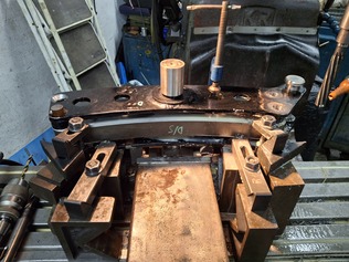
Reaming the mounting holes in the expansion links. -March 2026
We have had the fitted bolts for the expansion links in stock for some time. We bought a set of spares too, as we suspected that some trial fitting would be needed before final assembly. But now that we tried fitting the first bolt to the first completed hole, we found that it was rather too close a fit. The hole measures 18.00mm diameter while the bolt is 17.99mm. With a bit of friction, that's too tight to slide the bolt in without the use of considerable force. Andrew tried using some emery paper on one of the fitted bolts, but didn't make much progress.
At this stage we decided to put the fitted bolts to one side (to be dealt with later) and Dave was tasked with turning up a dowel that is an easier fit in the reamed hole. An offcut of 20mm bar was turned down, firstly to 17.96mm diameter (still a bit too tight) then 17.92mm diameter. A gentle tap with a mallet was sufficient to get the dowel into position.
The second dowel means that the assembly was now located accurately at three points, which should allow the other holes to be drilled and reamed consistently.
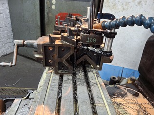
Andrew started working on the next hole, drilling the cover plates using the expansion link as a guide. It was a slow process, but progress was being made. To finish the hole, it was just a case of running the cobalt reamer through it. As Andrew got half way through, the expansion link work hardened and destroyed the cutting edges of the reamer. Some bad words may have filled the air!
The only other option we have is to use a boring bar in the boring head of the milling machine. It's slow to set up and slow to cut, but at least it has a tungsten carbide tip. Even this comes with its challenges; the boring bar would flex when the tip encountered a hardened patch of the expansion link material, so getting a constant diameter all the way through the hole was very difficult.
After two days work, Andrew had managed to drill/ream/bore out two 18mm diameter holes. By this time we were beginning to get despondent at the slow progress.
Fortunately the working party extended to the Monday, by which time Marek was back to offer advice. Andrew persevered with the drilling and boring operations, and by Monday afternoon, the third and fourth holes of the first expansion link assembly had been completed. He has clearly found a process which, while slow, seems to work. We are very much hoping that forming the bolt holes in the second expansion link assembly will be somewhat quicker and a lot less painful than those in the first.
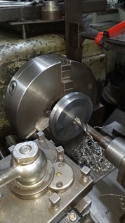
While not turning dowels for Andrew, Dave decided to turn up the pins for the reverser weighshaft cranks (the joint at the top of the lifting links) and for the joint between the bottom of the lifting links and the radius rods. Drawings and material were already at hand.
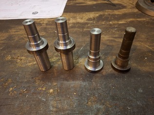
Each pin has a section on one end which needs to be of a very accurate diameter (20.01mm diameter) onto which a ball bearing is pressed. Other dimensions are slightly less critical, but are to defined tolerances nonetheless. Dave therefore started with the "difficult" end of one of the crank pins. Having pleased himself that he had achieved the tolerances required, it was time to turn the component round to machine the other end. At this point it became apparent that there was not much to hold in the chuck of the lathe. The only option was to hold the finely toleranced section. Needless to say, the workpiece slipped in the chuck, and gouged the surface it was holding. That's fit only for the scrap bin now!
After taking some time to calm down, Dave started making another pin, this time starting with the "easy" end. This worked well, and was easy to hold in the chuck when the pin was turned round to machine the "difficult" end. Having gained confidence with the accuracy of the lathe, Dave made steady progress, and after a couple of days had completed three of the four pins. If only he'd planned the first one more carefully all four would be complete by now!
New pins for the reverser weighshaft crank (Left) - March 2026
In between duties warming Linda up ready for operation on Sunday, Bobby was able to join us for part of the day on Saturday. He was tasked with drilling oil ports in the crosshead slippers. The ports in the top slippers were easy to locate, since a drill bit could be run through the port in the crosshead to drill a corresponding hole in the slipper.
The bottom slippers are more challenging, since the ports in the crosshead are not straight, which prevents a drill bit being run through them. Bobby had to resort to careful measurement of the positions of the holes in the crosshead (which cannot be assumed to be to drawing), and then transferring those measurements to the slippers. Everything went well, and the holes he drilled all align perfectly.
Cross heads with slippers test fitted fitted and oil holes drilled. - March 2026
Erle's machining skills were again in great demand, so he split his time between the NG15 and C2 Projects. On Saturday he made a replacement plunger for a mechanical lubricator. Even Erle was not immune to the frustrations of the weekend, and he had to spend a couple of hours extracting a broken drill. He didn't quite finish the plunger, but it's well on the way.
On Sunday Erle continued work on the C2 reverser latching wheel. After a number of turning operations, the overall external shape of the wheel is now finished. We selected a fairly hard steel (not as hard as the expansion links though) for the latching wheel, to minimise the wear seen on the original component, which meant that drilling out the centre of the wheel proved to be quite a noisy operation. The hole will require boring out to it's final diameter and a keyway broached into it, while the edges of the wheel will require 16 slots to be milled in it (using an indexing head), to complete this component.
New reverser latch plate being made by Erle. - March 2026
It seems that we all had our share of frustrations at the working party, but we have persevered. The problems have now been largely overcome, and we have methods which should avoid future frustrations. It starts to bring a sense of satisfaction when we realise that we are now over half way through some of the jobs which we were dreading (the expansion links!). So we have all come away quite pleased with what has been achieved.