C2 PROJECT
C2 Project News
Easter 2026
Easter working party report
After many months of working on the more major components of the motion, e.g. the crossheads and the expansion links, this working party saw attention turned to some of the smaller, but no less important, components.
The previous working party had seen Dave working on the replacement reverser weighshaft crank pins, with one being completed. So he immediately set to turning the second reverser weighshaft crank pin.
The ball bearings in the lifting links need to press onto the reverser weighshaft crank pins in situ, so can't be too tight a fit. Andrew therefore very carefully adjusted the diameter of the bearing seat on each pin until we are confident that we will be able to push the ball bearings on without too much of a fight. The challenge arises when it is realised that the tolerance on the bearing seat diameter is finer than the accuracy of the measuring equipment we have.
Using the existing reverser weighshaft crank pin collars as guides, Jack drilled a transverse hole through each crank pin to take a split pin. This completed the crank pins, and made them ready for fitting.
Since the reverser weighshaft is already assembled, it wasn't going to be possible to place the cranks under the hydraulic press to remove the previously fitted pins and to press in the new ones. Jack therefore found a short length of suitable diameter tube to place over the old pins. He and Andrew then used a boiler clamp to press out the incorrectly made crank pins, which fortunately came out reasonably easily.
Having left the new crank pins in the freezer for an hour or two, they could be fitted into the holes in the reverser weighshaft cranks by hand. A touch of Loctite made sure they will not come loose, even though their expansion in the holes should lock them in. Andrew and Jack even went to the trouble of aligning the split pin holes in the crank pins such that the split pins will be vertical when the engine is in mid gear! Great attention to detail.
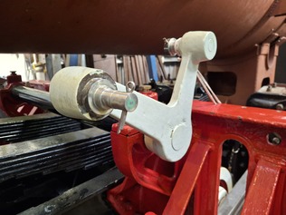
New reverser weighshaft crank pins pressed in, in situ. - Easter 2026
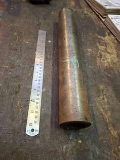
The original drawings show the oil pipes on the crossheads to be sealed with fibre gaskets. However, Jack found some copper bar, turned it and drilled it to the appropriate diameters, and then parted off thin slices to form copper washers.
With each copper washer tacked in position with a spot of Loctite, and the necessary studs screwed into the crosshead castings, Jack fitted the oil pipe assemblies. This proved a little more difficult than anticipated because the fixing holes in the oil pipe assemblies didn't line up perfectly with the studs. This is odd, since the oil pipe assemblies were originally fitted to the crossheads using studs in the same holes. Perhaps that explains why the original studs were a bit bent! Jack used a round file to remove a few thou of metal from the holes in the oil pipe assembles, and they now fit perfectly, with spring washers under the nuts to hold them in place.
Cross heads with oil pipes fitted by Jack. - Easter 2026
A week prior to Easter, Andrew had been at Boston Lodge finishing off the crosshead slippers. One of the final operations was to machine grooves in the whitemetalled surfaces to allow oil to spread out from the oil ports.
The original slipper design has just two transverse grooves, but in that design the slippers are made of bronze with no whitemetal. Since we have used whitemetal linings, we thought it prudent to ask the advice of the works' staff who are more familiar with whitemetalled crosshead slippers. It soon became apparent that there is no "right" way of doing it, with everyone having a different opinion.
Marek pointed out to us that the two transverse slots near the ends of the slippers, as shown on the original drawings, were probably there to prevent dirt getting under the slippers as much as spreading the oil out. He suggested transverse slots to trap the dirt linked by diagonals to allow oil to spread out. So Andrew used a spherical die grinder tool in a collet in a milling machine to form the grooves in all four slippers.
To finish this job off at Easter, Andrew used a Stanley knife blade to remove any burrs from the edges of the slots. Since the slots are machined in whitemetal, a knife blade can easily pare off any burrs.
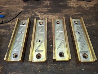
Oil grooves machined into the white metal of the cross head slippers - Easter 2026
Another job related to the crossheads was to make the keys to hold the little end bearing pins in place. These are conventional 12mm square keys. Andrew found some key steel slightly oversize, and milled it down to 12mm. He then used a cutting disc to cut the keys to length (key steel is harder than saw blades!). A little adjustment of the keyways in the crossheads with a hand file means that the keys are now a nice tight fit in the keyways, just as they should be.
Little end pins (Gudgeon pins) with the new keys machined and in place. - Easter 2026
The combination levers each have a fork at their lower end, into which the union links fit. One of our exiting combination levers had a 22mm gap in the fork, wide enough to accept the 21mm wide union link. But the other had a gap of only about 19mm. To compensate for this, the Chinese had milled away part of the front surface of the corresponding union link by a few millimetres; not a very elegant solution. It seemed sensible, therefore, to open out the gap in the offending combination lever fork. After a quick lesson on operating the Archdale milling machine, Jack used it to mill out the gap to 22mm.
Dave was rather enjoying using the 17' DSG lathe, so continued to make pins for the motion. He had drawn up pins for the union link bearing pins, assuming that the union links were fitted the same way round as the lifting links. But close inspection of photographs showed that the union links had originally been the other way round. A quick redesign of the pins was therefore required.
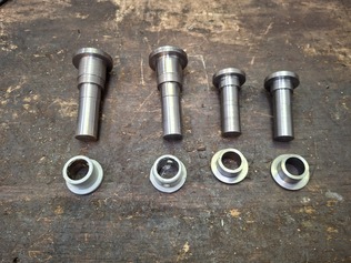
New pins for the lifting links/radius rod (left) and Union link/combination lever (right) - Easter 2026
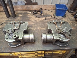
One end of the union link is centred on the little end bearing. To achieve this, the pin is carried on a bridge piece, which bridges the little end bearing pin and its retaining bar. The bridge pieces are nominally machined as one piece, incorporating the pin for the union link bearing, but we noted that one of ours has already had the pin replaced.
The pins on both bridge pieces were very worn, which would make it difficult to fit a ball bearing without the risk of the inner race slipping. Furthermore, the collars on the ends of the pins were a very loose fit. We therefore decided to replace the pins on the bridge pieces.
For a start, Dave used a hand file to remove some burrs on the underside of the bridge pieces, so that they would sit flat. Andrew then cut off the old pins. Mounting the bridge pieces on a milling machine, he machined the top surfaces flat (to remove some wear damage). The bridge pieces were then drilled and reamed to accept new pins.
Adapting the drawing he had prepared prior to realising the union links fitted the other way round, Dave turned up two new pins for the crosshead bridge pieces. He also bored and turned up two collars to fit on the end of the pins. It wasn't a quick job, as the pins require fine tolerances where they push into the bridge pieces, and where the union link ball bearings will press onto them. Once complete, Andrew pressed the new pins into the bridge pieces.
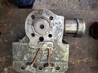
Cross heads with bridge pieces over the little end pins (gudgeon pins) to mount the union links. Easter 2026
The pins which connect the the union links to the combination levers had an M16 threaded portion on their ends, with the pin held in by a nut with spring washer underneath it. We have found it difficult to accurately hand cut M16 and bigger threads, so to make the pins as first drawn by Dave, we would need to turn the threads on a lathe. This is a very slow process. Dave looked at the original drawings, which utilised plain bearings instead of ball bearings for the union links, and realised that the pin at the combination lever end originally had a collar rather than a nut and spring washer. While this arrangement requires a couple of extra components to be machined, it would be quicker than turning a thread on the end of each pin. Dave therefore adapted his drawing again, and set to making new union link/combination lever pins. A couple of collars, identical to those fitted to the crosshead bridge piece pins, were also made.
Two of the pins which Dave turned at the previous working party connect the bottom of the lifting links to the rear ends of the radius rods. These have been made slightly oversize, to allow for any wear in the holes in the radius rods. Bobby found the reamers which Dave had identified to size the pins, and used them to ream out the holes in the radius rods. After a little fettling by Jack, the pins are now a nice fit.
The other holes in the radius rod (for the expansion link die block pin and the pin connecting the front of the radius rod to the top of the combination lever) had steel bushes in, some of which were loose. Jack found a suitable piece of steel to use as a press tool, and used the hydraulic press to remove any bushes that hadn't already fallen out.
While pushing bushes out, Jack also removed the bushes from the reverser rear reach rod. These will be replaced with plastic bushes in due course.
A job which has been awaiting attention for many years is the removal of one of the valve stem sleeves. The sleeves fit onto the valve stems to provide a wearing surface for the seals. They are held on by large nuts at the end of the valve stems, so should be loose when the nut is removed. One was loose and came off with no trouble. The other had seized onto the valve stem. We are now at the stage where we want to machine the sleeves, so we need both of them off. Fortunately the task turned out to be easier than we feared. Bobby found a large block of wood, held the valve assembly above it, and dropped the valve stem onto the block of wood. The shock was enough to dislodge the sleeve, and it was off.
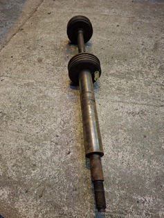
Valve Spindle with sleeve. - Easter 2026
Valve spindle sleeve removed. - Easter 2026
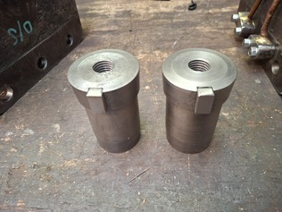
Using a wire wheel, Bobby removed any corrosion and dirt from the surfaces of the valve stem sleeves. This readies them for machining. We would ideally like to grind the sleeves, since grinding gives a very high quality surface finish and removes the minimum amount of material. However we have been unable to find anyone with access to a cylindrical or toolpost grinder, so it looks like we will have to resort to very careful turning on a lathe.
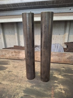
Valve spindle sleeves ready for grinding (or turning) - Easter 2026
Another job which has been on our list for a considerable time is the fitting of split pins to the castle nuts at the front of the slidebars. This is not a simple task, since access is quite restricted. Fortunately Jack managed to find a 5mm drill with a long shank and a cordless drill which has a narrower body than most of our power drills. Using these he managed to drill holes in the studs holding the slidebars in place. Suitable split pins were then fitted and bent to lock everything in place.
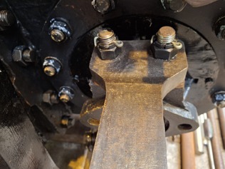
Slide bars fitted with castle nuts and split pins. Easter 2026
Many of the pins which link motion parts are fitted with small keys. These stop the pin rotating in the main component and force movement to occur at a ball bearing or where any wear can easily be repaired (i.e. with a bush). The "keyways" take the form of a small shallow milled slot radiating from the hole in the main component and a small drilled hole adjacent to the head of the pin. The key itself is a short length of round bar which fits into the hole in the pin and projects into the slot in the component. The key cannot fall out because it is covered by the head of the pin. Simple but effective.
The pins which connect the return rods to the expansion link cover plates, the pins which connect the radius rods to the top of the combination levers and the pins pins which connect the reverser reach rods to the intermediate crank all need keys as described above. Jack drilled a short 3mm diameter hole under the head of each of these pins. He found a length of 3mm diameter bar (actually a welding rod!) and cut sections off it to make the keys. To prevent them getting lost before we fit the pins, he Loctited the keys into the pins. One or two of the keys needed a touch with a file before the fitted comfortably into the keyways in the main components, but this was a simple task.
We have four return rods (eccentric rods), two which came off the engine and two spares. Dave and Jack measured all four rods to try and assess which would be best to use. All the critical dimensions seemed to be correct, but those off the engine exhibited some side wear where they interface with the expansion link cover plates and were in generally poorer external condition. It seems sensible to therefore use the spare rods.
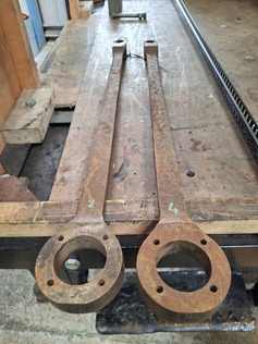
The two spare return rods (eccentric rods) chosen to be used. - Easter 2026
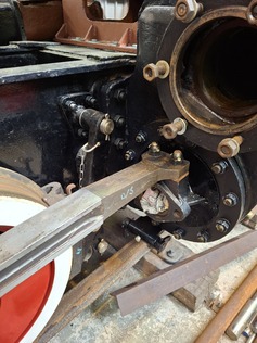
The bearing which holds each return rod onto the corresponding return crank is a roller bearing fed by grease. There is a port in the bearing housing for grease to be injected into the bearing during maintenance, but the Chinese had left this port open. To prevent dirt entering the bearing we want to fit a grease nipple. Jack found a 1/8"; BSP tap and used it to thread the exiting grease ports. He also sourced a couple of 1/8" BSP grease nipples ready for fitting.
As if Jack had not done enough for us already, he then took one of the return cranks which Andrew had built up with weld at a previous working party, and used the Archdale milling machine to mill the repaired surface flat. The crank is still a little thinner (only by a millimetre or two) than the original drawing specifies, but at least we have a flat surface to measure against. We suspect that the return cranks will need to be spaced further out than the original design, to clear other parts of the motion, so the reduced thickness may ultimately be a benefit.
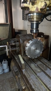
While all of the above was going on, Erle was continuing work on the reverser. The reverser latching wheel had been turned to size at the previous working party, and was ready for the notches around the edge to be machined. Erle found the indexing head, and after watching a couple of YouTube videos, fathomed out how to use it. Andrew had purchased a carbide tipped milling cutter for the job, and Erle was pleased to find that it cut the notches perfectly with no discernible wear. With the 16 notches all milled, the latching wheel is beginning to look very smart indeed!
Erle machining the notches in the new reverser latch wheel. - Easter 2026
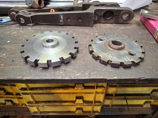
New and old reverser latch plates side by side. - Easter 2026
Next task was to broach a keyway into the hole in the centre of the latching wheel. We have a suitable broaching tool, but Erle needed to make a supporting piece. The support takes the form of a cylinder of steel with a slot along it in which the broaching tool runs, and a flange to stop the support pulling through the hole in the workpiece.
Erle turned a piece of steel to form the support. However, none of the milling cutters he could find at Boston Lodge were sharp enough to cut the slot. After some exasperation, we have offered to buy a decent milling cutter to allow Erle to complete the job.
Although the keyway is on pause, there were other tasks on the reverser which Erle could get on with. He drilled the holes in the wheel and handle to allow them to be fixed together. The holes in the wheel were tapped, and the holes in the handle countersunk. Cap head screws now hold the two components together.
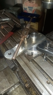
Erle tapping to holes in the reverser latch plate to fix the handle. - Easter 2026
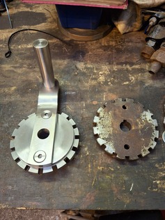
New reverser assembled (left) and the old latch plate (right). This really is an excellent piece of machining by Erle. - Easter 2026
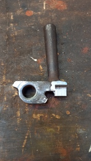
Andrew had previously built up the worn reverser latch with weld, so Erle machined this back to its intended dimensions. The latch now fits perfectly into the notches in the wheel, with minimal play. How Erle managed to get such square cornered cuts still baffles us!
Reverser latch built up with weld and re-machined by Erle to the correct dimension. Easter 2026
To summarise, we have made tremendous progress over Easter! We started the working party with a long list of jobs on the whiteboard, but really ploughed through them. A special thank you must go to Jack who was, at times, completing jobs faster than we could think of them! And the work Erle does never ceases to amaze us, for which we are eternally grateful.