C2 PROJECT
C2 Project News
July 2024
Update from the July 2024 Working Party
The July working party was a relatively small affair, with just Andrew, Dave 1 and Erle in attendance, but we got some useful tasks done nonetheless.
Since we have lowered the cab of the locomotive, and will have to do the same for the top of the chimney, we would also like to lower the dome of the boiler a little to avoid a 'hump-backed' appearance. To lower the dome, we need to be sure that the equipment inside it will still fit. Riser pipes can easily be shortened, but the regulator valve is a big casting which we don't want to replace. So the question is; how much clearance is there between the regulator valve and the inside of the dome cover?
To answer the above question, all we have to do is place the regulator valve casting in the dome and measure the clearance through the access hatch in the dome cover. Sounds easy, but the dome is high up and the dome cover is very heavy, so scaffolding and lifting gear is required.
The siding in the C2 Shed is not long enough to position the dome under the A-frame crane with the tender coupled to the engine. So first stage was to use a diesel shunter to move the locomotive out of the C2 shed and over a pit where we could remove the engine-tender drawbar. Leaving the tender outside, we then shunted the engine back into the C2 shed and positioned it with the dome under the crane.
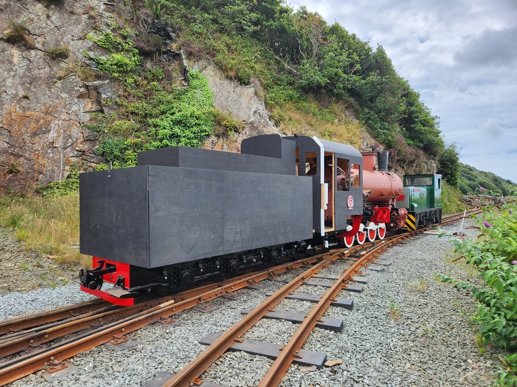
Towing the C2 out of the shed to move it over a pit.
The C2 positioned over the pit in Boston Lodge 19 road to remove the drawbar between the loco and tender. A rake of South African B waggons happened to be already over the pit.
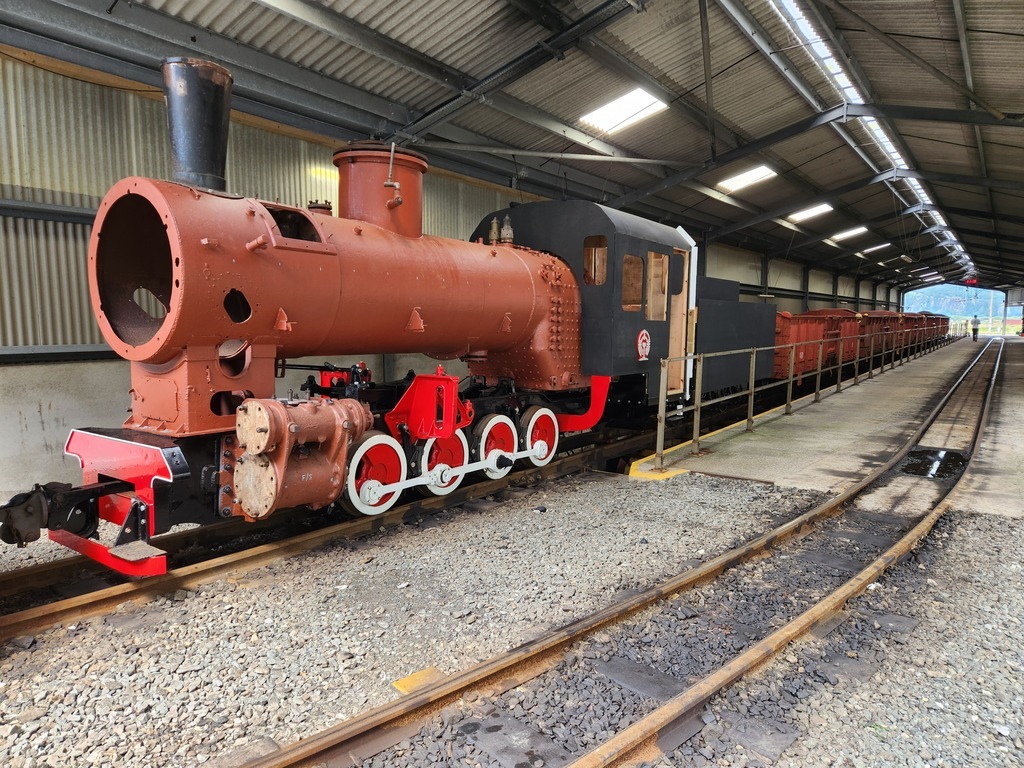
Next stage was to borrow some scaffolding and to assemble it next to the engine. We could then fit shackles to the lifting lugs on the dome cover. After some searching we found a suitable length lifting strap, and the dome cover could be lifted off.
The regulator valve casting is not light, but with care can be safely lifted by hand. It was therefore lifted up into the dome and fitted onto the studs on the J-pipe. Using the crane again, the dome cover could then be replaced. Taking the actual measurements was very easy, thanks to the access hatch in the dome cover directly over the regulator valve.
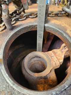
Measuring the clearance inside the dome.
The whole process then had to be reversed, although we have not re-coupled the engine and tender as we want to access the cab, which is easier done without it being coupled to the tender.
It took most of the day to obtain just two measurements, but there was no other way of obtaining them safely. Since the regulator valve is not complete, we will have to carry out some calculations to determine how much clearance there really is inside the dome, and hence if we can lower it a little. But we now have the essential information.
Erle was once again working on the reverser baseplate. This is an incredible amount of work and done to a very high standard. We are greatful that Erle can continue to come to progress this important piece of work.
The following day we returned to making things. Dave 1 turned up the two remaining Vesconite motion bracket bushes for the expansion link pivots, while Andrew turned up the first of the four stainless steel expansion link trunnion sleeves which will fit in the bushes Dave made.