C2 PROJECT
C2 Photo Album
album:November 2021
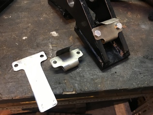
A new design of brake block support springs for axle 2, where the clearances around the motion bracket meant that the original design did not work.
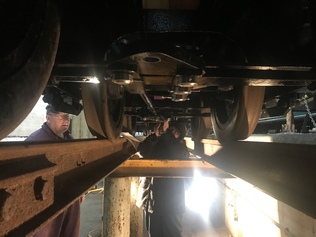
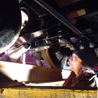
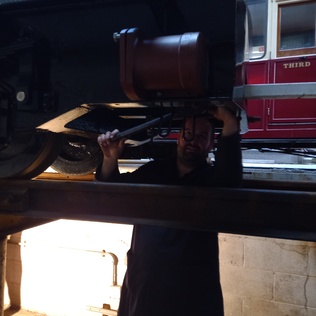
Helen and Dave 2 install the tender brake gear on the carriage inspection pit, now 19 road.
A fiery sunrise on Sunday morning, seen from above Porthmadog Harbour. Boston Lodge is visible in the distance.

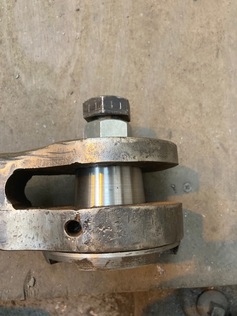
Jig assembled and holding cover plate in place.
Jig assembled and holding cover plate in place.
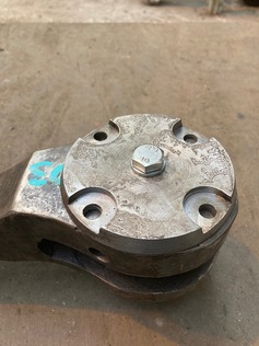
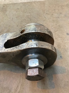
Jig trial fitted to the tapered hole in the coupling rod knuckle joint
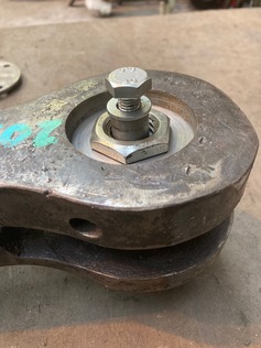
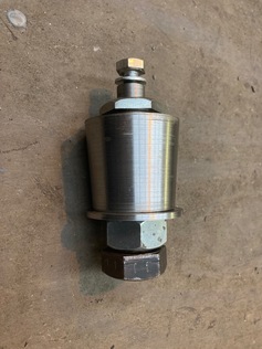
Jig trial assembled
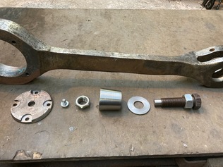
Component parts of the coupling rod knuckle joint jig

Andrew prepares to drill one of the new cab support brackets.
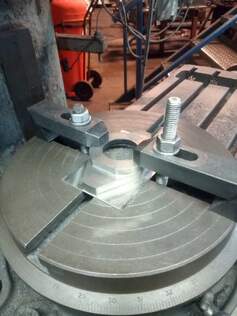
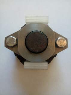
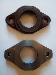

Contrast of old and new: this is the turbogenerator regulator spring and the two parts that it interfaces with, all replaced with new parts made or specified by Erle.
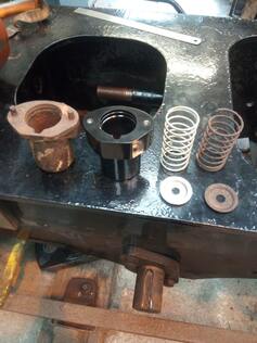
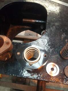
The new parts assembled together.
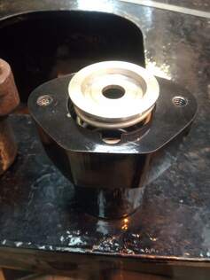
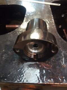
Cab support bracket components tacked together.

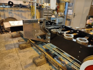
Cab support bracket trial-fitted to the loco frames
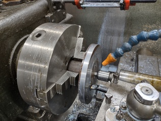
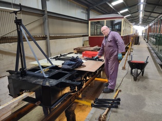
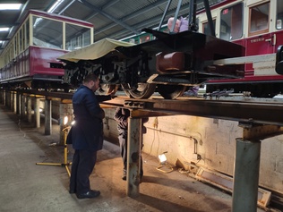
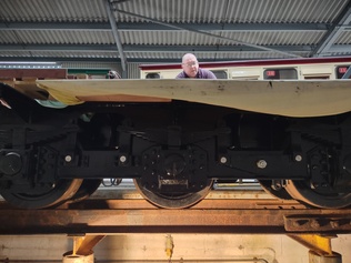
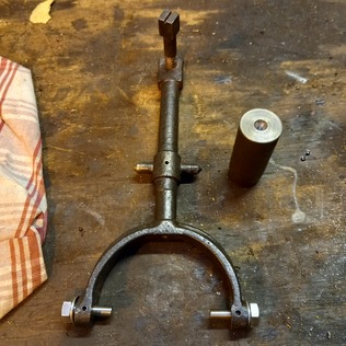
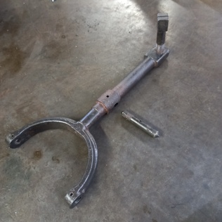
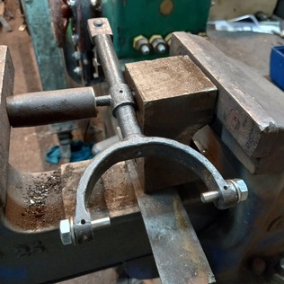
The pivot shaft removed from the yoke arm, using a combination of heat and a special pressing jig.
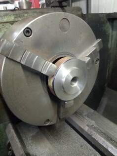
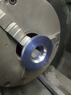
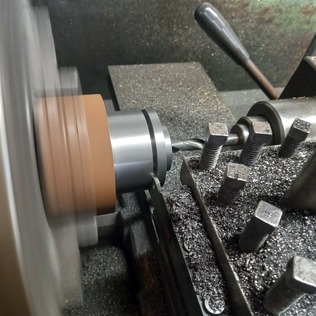
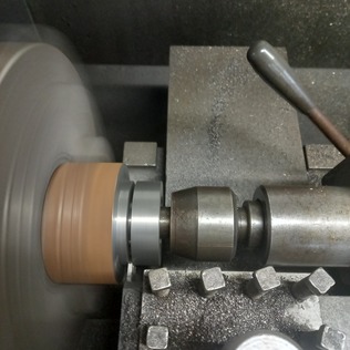
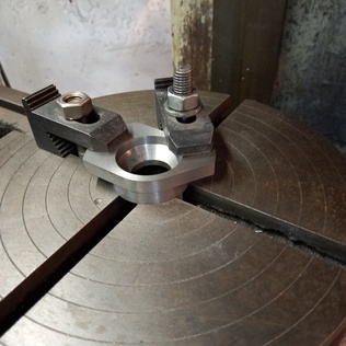
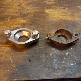
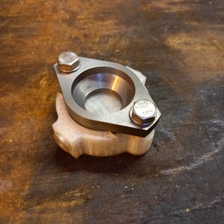
Machining jig for the graphite carrier.
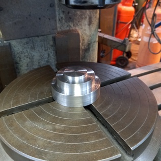
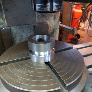
The graphite carrier mounted on the machining jig.
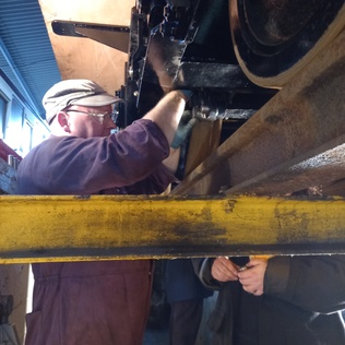
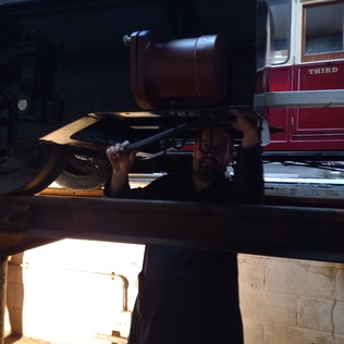
Paul uses a ratchet drill and reamer to ream out the tender steam brake cylinder bolt holes. This was easier to do over the pit, though still very time-consuming with the restricted access and no room for a power tool.
Helen and Dave 2 assemble more tender brake gear parts.
