C2 PROJECT
C2 Photo Album
album:February 2023
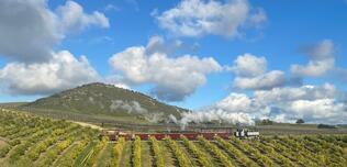
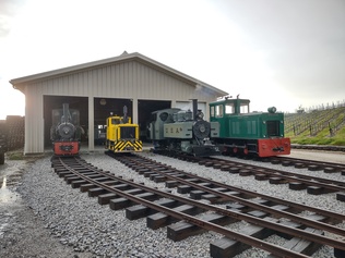
Andrew drives a train on the Norgrove Railway in California. This is a private agricultural railway owned by a former FR driver. Photograph: Ben Abbott
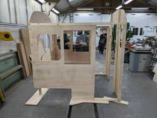
The wooden cab mock-up assembled on the ground, in the carriage works. Front 3/4 view.

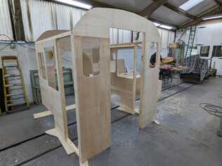
The wooden cab mock-up assembled on the ground, in the carriage works. Rear 3/4 view.
The wooden cab mock-up assembled on the ground, in the carriage works. Side view.
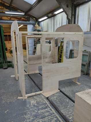

The cab mockup reduced to a flat-pack, ready for assembly onto the loco. Materials were also provided for the roof, to be fitted after final assembly.
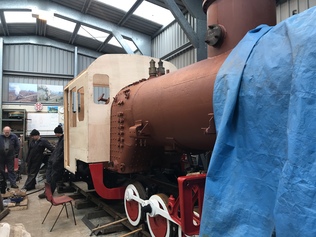
The cab sides and ends assembled onto the loco. This gives a good idea of the revised proportions of the cab to suit the FR loading gauge: we have attempted to retain the original character in something slightly smaller than our loco's original cab.
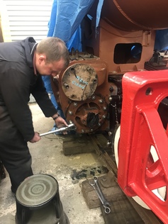
Dave 4 tightens the cylinder cover nuts on the newly-installed studs.
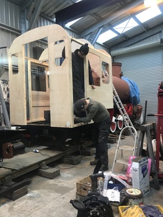
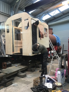
Julian (from the WWF team) carries out some minor surgery on the wooden cab, while Bobby holds it in place.
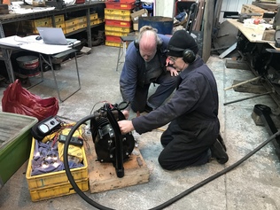
Erle and Dave gradually increase the air supply to the turbogenerator, monitoring the voltage and rpm while the lamps get brighter.
At 3000rpm, the turbogenerator was producing the rated 50V. This was with a relatively small electrical load and powered by air at around 100psi. We will put together a higher-rated load bank next time.
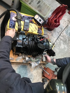
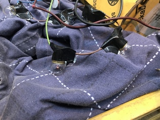
The first glimmer of light from the turbogenerator. After all Erle's careful work on the mechanical side, and the outsourced electrical attention, it does actually work!
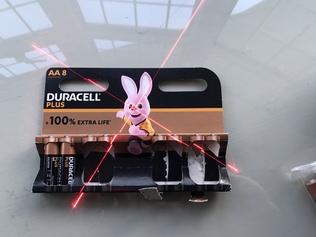
Laser target clamped to the slidebar, set at right angles and with the outer faces flush.
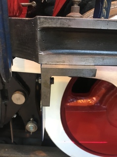
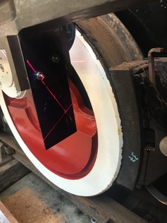
Using the laser to mark a circle on the target plate. The laser itself was attached to a rod accurately centred in the cylinder bore, which was rotated to produce the circle.
Overview of the laser alignment.


Dave 2 helps to assemble the wooden cab mock-up onto the loco.
Julian (from the WWF) carries out some minor surgery on the wooden cab, while Bobby holds it in place.
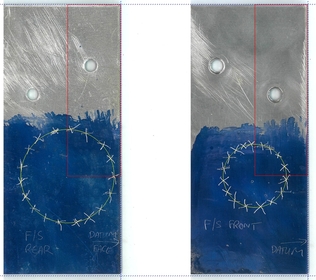
Determining the slidebar offsets from the laser target plates.